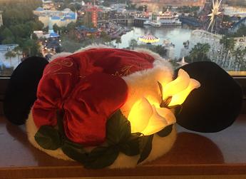
 In a previous post, I showed how to add some Made With Magic to fabric rose buds. Here, we do something similar by adding MWM enabled roses to a holiday hat. While the original hack didn't require any soldering, that setup proved too fragile for a wearable application. To handle the rigors of an article that is likely to be tossed around a bit and stuffed into suitcases, the connections need to be as sturdy as possible - soldering required.
This hack will require a few more skills than the previous one but will result in a product more suited for duty as a wearable item. And isn't that what most park-goers are looking for?
The Hat
 The Mrs already had a Minnie Santa Hat she bought during a visit to one of the parks about a year or so ago and thought it would be nice to add some holiday lighting to it this year to liven up the seasonal festivities. She also has a thing for roses and remembered the hack I'd recently finished. So adding some hacked roses to her hat became the goal. I don't know if this particular hat is still available for sale or not. But I'm sure folks out there can come up with other suitable targets for your fiendish plans.
Picking the MWM device to victimize
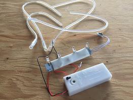 Since this hack will require running some wires to externally located RGB LEDs, it's easiest if the starting MWM board lends itself to easily replacing the existing LEDs and attaching a new set of wires. For this purpose, through-hole board connections are easier to work with than surface mounted.
The two MWM products that use through-hole LED attachments are the Wand and the Glove. The Wand provides a more compact board to work with and has two LED connections to hook into, which is all that is needed for this hack, but other considerations favor using the Glove components. For one thing, we're gonna need to power all this and the extracted Glove components are already hooked to a battery assembly by wires that are long enough for this hack. The battery holder has the on/off switch while the Wand switch is on the board. And, the Glove IR receiver is already wired and off the main board while the IR receiver of the Wand is surface mounted on the PCB. When considering that the PCB is gonna be buried behind a portion of the hat's bow, the Glove setup is a distinct advantage. A quick check confirmed that both the battery holder and the PCB fit behind the bow such that they can be concealed with a little sewing. So the Glove board was chosen.
Now, extract the goodies
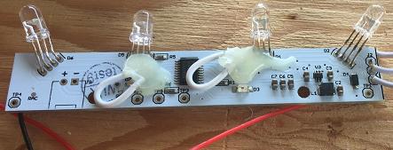 The basics for how to extract the MWM components from a Glove have been covered elsewhere. Follow that link if you need instructions. After carefully removing the outer sheath around the Glove's circuit board, we notice two things. First, something new has been added since the previous version (v1.2). There are two new wires and a mess of hot glue on this board that weren't on the previous (v1.2) board. The connections those wires make to the board proved to be extremely fragile. That hot glue sticks to the surrounding sheath when removing it. I manged to pull off one of the tabs the wire connects to on the board the first one of these I took apart. That caused a loss of blue light from the two LEDs on the right side. I tried to repair the damage and couldn't figure out how to make it work. In essence, I wrecked it. So that's one take home lesson - heat up the sheath directly over that hot glue mess before trying to separate the two and treat that wired region with utmost respect. In fact, we only need two connections for this hack. I simply replaced the two outer connections and left the inner two alone.
Another caution: the wires that connect the IR receiver to the board seem to be just looking for a reason to come off. Try not to give them one. Look closely at the pic above and you'll see that the upper wire has already proclaimed it's independence and released itself from it's bonds. You'll want to provide some sort of stabilization to those connections. Maybe add a small dose of hot glue or some potting resin to those as soon as the assembly is extracted.
Modify the board connections and wire up the LEDs
The outer two LEDs were removed from the Glove board and replaced with JST connectors. The two inner LEDs were simply covered with black electrical tape. That seemed to do the trick for this project. Of course, you're more than welcome to come up with your own uses for those extra two LEDs.
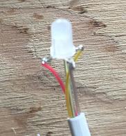 Diffused RGB LEDs were substituted for the water-clear LEDs that came with the product. Their leads were bent outwards, trimmed and soldered to the wires in a 4 conductor telephone cable that I picked up at a thrift store. The main trick is keeping track of the orientation of the leads such that the proper wires are soldered to the appropriate pins.
It's also important that not too much of the cable's insulation is removed. When the rose is reassembled, you want the lower green sepal to be resting on the cable's sheath, and not the skinnier wires. That way you get a snug fit that holds everything together without any wobbling.
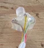 Once the wires are soldered in place, some hot glue is added to both insulate them and to provide a glob that will nestle nicely into the bottom of each rose bud. Push those exposed wires down toward the LED as much as you can when you glob the bottom of the LED with hot glue.
If you haven't done so already, eyeball about how long your wires will need to be to cover the distance between where you'll want the flower to be positioned and where you'll conceal the PCB under one of the halves of the bow. Consider that you'll also be soldering on the wires to connect to the JST sockets. Once you have your estimate, cut the wires cuz the next part involves snaking the wires through the parts of the flower.
Prep the rose bud
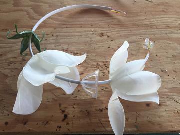
The rose buds that I bought at Dollar Tree, consisted of basically 6 or so pieces. They're held together by a green plastic plug you'll locate in the center inside the bud. Start by pulling that out. After that, you should be able to carefully remove the other 4 parts of the actual bud from the stem.
Then you're ready to reverse the process and thread the wired LED's wire back through the parts of the flower. Check the picture to the left. It shows how this should look. And, once you've pulled the parts back together, you'll have something that looks like the picture on the right.
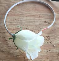 Now, solder the male JST connector wires to your LED cables. This is where it's particularly important to get the orientation correct.
To make the cable look more flowery, wrap it with florist tape as was done in the previous hack.
The Mrs didn't want her hat to be cut. So the cable had to be run on the outer surface of the brim. It was stitched in place using green thread. Initially, those long green "stems" traveling all the way back to the bow looked pretty bad. To rescue the look, some of the leaves that came with the initial assembly were hot glued into place to cover up most of the wiring.
The battery holder was tucked behind the half of the bow closest to the buds. The side and bottom edges of the bow were stitched down with red thread to secure the holder in place. The top was left open to allow the holder to be removed to change batteries and to access the on/off switch.
The PCB was tucked under the other half of the bow and virtually the entire rim of that portion of the bow was stitched down, leaving just enough of an opening to wiggle the IR receiver through the top.
Positioning the IR receiver was a bit trickier than I thought. The bow will pretty much completely block the IR signals if it gets in the way. I settled for a position on the top of the hat concealed just a little behind some of the white 'fur' of the brim. It was useful to put a little mounting tape on the back of the IR receiver's board to hold it in place while experimenting with location. Once satisfied, that sucker was stitched down to hold it in place.
The final result is shown in the first pic above. Happy wife.
