The previous article gave power to the people
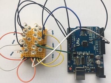
 In the first article on using Arduinos to control Made with Magic products, we covered a lot of ground. The emphasis was on getting a lot of infrared signal output from the Arduino. I showed that a single Uno can drive 18 IR LEDs without having to resort to additional transistors or mosfets and without requiring additional external power input. That setup will probably generate enough signal to hit most targets in a typical room in a house.
If you went with the suggested Arduino clone, the 20 IR LEDs from the source linked to and added some resistors, mini breadboard and connection wires, you're probably up and running for under $20. That didn't hurt too badly, did it? If you got bold and took a chance with one of those really cheap clones available on eBay and utilized some stuff you had laying around, it's possible you made it happen for under $10! And, if you took a peak at some of the suggested links to the actual Made with Magic codes, you now may be able to get a whole room full of devices to obey your command. What could be better? How about the ability to control individual targets?
Resisting the Borg's plot to take over the room
Some of the Made with Magic products are designed to synchronize their light effects with one another, especially the Ear-type products. When that happens, they're just doing what comes naturally. That's kind of fun in the Parks as it gives your little group an aspect of solidarity. However, it's not always an ideal behavior for re-imagined (hacked) creations back in the living room. When the hanging lamp, the castle and the flowers all start flashing the same effects at the same time, it's as if they've somehow conspired together and are amassing strength prior to seizing control of the room. Ominous and annoying. What I used to do when that happened is just shut them off or cold bloodedly blast a code for some solid color just to make them behave. Rebellion squashed.
The early days of working with multiple Made with Magic items taught me a couple of lessons. One, most of the time I don't want them to be doing their flashing thing, I just want them to function as simple lights. And two, the different hacks have different personalities and I want the lights to reflect and support those unique personalities. Using a controller that blasts the same signal throughout the room, it's possible to tame the flashing, but, by itself, it can't set individual targets to give different responses. That requires a different approach that we'll discuss next.
Supporting diversity
 In this article, we'll continue to leverage the ability to bit bang Arduino pins that was described in the first article. But, instead of turning all the pins on at once and flooding the room with the same signal, we'll sequentially turn on individual pins controlling LEDs that are carefully aimed at individual Made with Magic targets and send different codes out to each target to achieve individualized effects. I'll also share the little bit that I know about the Made with Magic codes that are designed to support addressing different targets and how to use them.
Advanced warning: it takes a good deal more fiddling to make this work. More wires. More resistors. And it usually works better with, or flat out requires, two microprocessors. But the extra effort and expense can be well worth it! It can make coexisting with Made with Magic hacks a lot more enjoyable and even render them downright useful. It really changed the way I think about these hacks and the roles they can play in our home. Maybe it will do the same for you, too.
Turning IR LEDs into spotlights
 If you went with the Uno model that was recommended in the last article and want to target 6 or fewer Made with Magic items, the good news is that you probably won't need to change the program from that article to make this work. The tricky part will be limiting the IR signals to the intended target and ONLY the intended target.
Infrared light is just light. It will happily reflect off surfaces, including the surface of the targeted item, and bounce around the room also hitting unintended targets! If your targets are located close together, it will be harder to keep the light from spilling over. To make this work, the LEDs attached to each pin will need to be pointed directly at their target. Won't work if they're all nestled into the same breadboard. That means you may need more and/or different connecting wires. Usually, fewer LEDs will be required per pin/target. It often only requires one LED for each. That means changing resistors. A 1.5V IR LED consuming 20mA of current needs a 178 - 180 ohm resistor. Two LEDs in series running at 20mA will need a 120 ohm resistor. But those are often just starting points. Higher resistor values may be needed to further limit the amount of light from each LED if surrounding targets are also getting the signal.
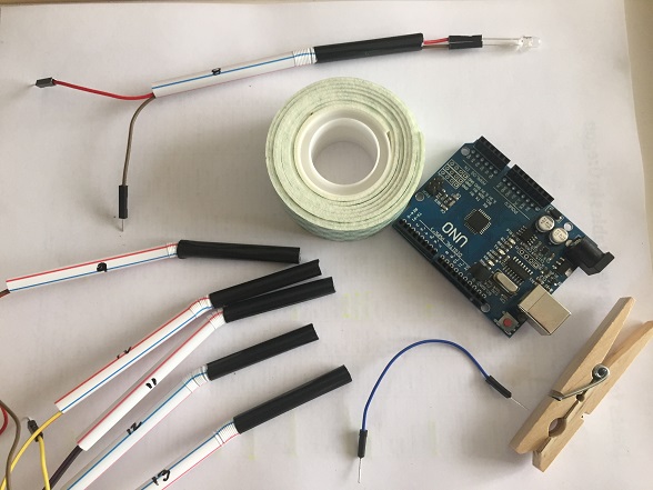
 Narrow beam LEDs, such as the ones described in the first article, are essential. I've found 1/4" diameter drinking straws to be particularly helpful for both aiming and restricting the IR beam. A 5mm LED slides perfectly inside. The straws will probably require covering the outside with electrical tape, paint or shrink wrap as plenty of IR light tends to escape out the sides of most straws if that isn't taken care of. Of course, it doesn't have to be a straw. I only suggest those because they're cheap and readily available. I've also tried 1/4" drip irrigation tubing with 3mm IR LEDs. That also works, but is not a very practical solution.
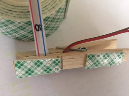
To hold the bases of the straws in place, I went with clothes pins from the Dollar Tree fastened to the back edge of the shelf with mounting tape. The larger hole in the clothes pin fits the straw nicely. The smaller hole fits the wires perfectly and provides a little strain relief. And the mounting tape does what it does.
Testing the setup
 Assuming you've replaced the resistors, attached the wires, slipped the LED into the straw and have it pointed at it's intended target, you're ready to give it a test. Plug the Arduino into the computer's USB port. Fire up the Arduino IDE software. Make sure the board matches what you're using and the port is set correctly. Then open the Serial Monitor. Check to see that the setting in the lower right corner (baud rate) is 115200. The part of that window to focus on is the segment shown in the table with the pin data.
| pin | code | color |
| 8 | 8C 0F A9 11 24 61 D0 05 FF | solid blue |
| 9 | 8C 17 A9 19 24 62 D0 05 FF | solid green |
| 10 | 8C 1F A9 21 24 63 D0 05 FF | solid cyan |
| 11 | 8C 27 A9 29 24 64 D0 05 FF | solid red |
| 12 | 8C 2F A9 31 24 65 D0 05 FF | solid magenta |
| 13 | 8C 37 A9 39 24 66 D0 05 FF | solid yellow |
That data is telling you that an attempt was made to assign values (hexidecimal notation) to variables in the targeted Made with Magic items that may be used to single them out when using the appropriate Made with Magic commands.
Since the Uno only has 6 pins to test, we can use the basic color palette (0x6?) for this test. When the codes in the test table (hex) are copied, pasted into the command line of the Arduino IDE's Serial Monitor and submitted, the colors indicated should be displayed by the appropriate targets. If that's what you see (check out the video below), great. You've got it made. If not, don't worry. Some additional fiddling should make things come around.
Interpreting the results and troubleshooting
When I think about it, there are two general categories for what can go wrong:
- Some targets don't seem to get the signals and continue flashing their built-in effects
- Multiple targets respond with the same solid color
Why the targets don't receive the signals
This first category covers when targets simply didn't get the commands. Here's some reasons why that might occur:
- The targets weren't turned on when the Arduino started up and sent the initialization signals. The codes are only sent once during the Arduino's startup sequence. If the MWM targets aren't on when that happens, they won't receive the signals. Make sure all the targets are powered up and running, then restart the Arduino and try again.
- LED aim is bad. Narrow beam width LEDs require an accurate aim. It's easy for the aiming device, whatever is used, to get knocked out of alignment. So verify the aim is still good. It's also possible that the IR receiver on the Made with Magic board is not aligned favorably for the IR source to reach it. Figure out where that receiver is and determine if something might be blocking the signals.
- LED signal too weak to reach the target. This can become a problem when a single IR LED is the source and the target is more than 12-15 ft away. To correct this problem there are two fundamental choices. Extend the wiring to get the LED closer to the target or try additional LEDs, connected in series, to increase the signal. Remember to use the appropriate resistors when altering the number of LEDs in series.
- Wiring incorrect and/or came undone. If you're like me, you'll probably skip soldering wires to the LEDs. The gotos are the typical Dupont-style breadboard connecting wires. They are convenient and come in a variety of male/female ends. Those do work but are very easy to pull apart and break the connections. Very easy. And sometimes the male/female connections are kind of loose to begin with. It's also not hard to get the LEDs connected backwards. If things aren't working, check the wiring and connections.
Why multiple targets get the same signal
The second category can be more labor intensive to solve. Essentially, there are two basic reasons for this problem: the aim of the signal is not exclusive and/or the signal is too strong and is indirectly reaching other targets.
- Aim is bad. If care isn't taken to make sure the aim it true, there will be problems. A naked LED pointed in the general direction of the target is not likely to work. In almost all cases, the LED needs to be slipped into some type of tube that can be used to aim the signal and prevent light from escaping out the sides. If a straw is used but the outside of the straw isn't covered with something like electrical tape, etc, light will go out the sides and hit unintended targets.
- Targets are too close together with respect to the IR source. The 'narrow beam' IR LEDs have a beam width around 20 degrees and are usually good for 15 ft or more when driven by an Arduino with the appropriate resistors. Using basic trig functions, the tangent of 10 degrees with an adjacent length of 15 ft would give a horizontal (opposite) coverage of about 2 1/2 ft. Double that to account for the 20 degree angle of the LED and it's clear that targets placed within 5 ft of each other and targeted by a source 15 ft away are quite likely to receive the same signal. Extrapolating those results, if our targets are about 1 foot apart, the source can't be more than about 2 3/4 ft away without running the risk of hitting unintended targets. Sticking the LED in a staw with opaque sides delays the light from spreading out and helps this problem a little. But the take home lesson is this: if the targets are a foot or so apart, it won't be possible to setup the IR LEDs across the room and hope that will work.
This is one reason why I mentioned, earlier, that this approach may work best when two Arduinos are used. One Arduino may be tucked away close to the targets and simply handles the initialization of those targets, while another Arduino is located further away and is connected to the computer that will generate the subsequent Made with Magic commands. I'll have more to say about this in a bit.
- Signal is too intense and is bouncing off surfaces. In the last bullet item, the need for the IR LED to be fairly close to the target was explained. However, as the LED comes closer to the target, a new problem may arise. It becomes more likely that the light from the LED will be sufficiently intense to strike various surfaces and bounce off to other targets, unintentionally programming them.
I've found walls to be a common source of the problem. For targets placed on a shelf, you want the LED located against the wall pointing OUTWARDS, away from the wall and towards the middle of the room. Pointing the LED towards a target with a wall right behind it will often cause problems.
Because the signals are sequentially sent out the respective pins, the most important thing to avoid is bouncing signals back to the targets that have already been programmed. It doesn't matter if some of the upcoming targets receive earlier signals. So, when initializing a row of targets, always aim DOWN the row towards the upcoming targets and away from the targets already initialized.
If problems persist, try putting some sort of decoration between the troublesome targets to block the scattered light. And if that doesn't do the trick, the amount of light being emitted will have to be diminished. Try putting a piece of electrical tape over the open end of the tube with the LED. Then poke a small hole in the tape and see if that works. If it looks like the target isn't receiving the signal, make the hole in the tape a little bigger and keep trying until it works. A geek-ier approach is to increase the resistance by using a stronger resistor. Try a 390 ohm resistor. If that doesn't do it, try an 820 or 1k ohm resistor. Eventually, one of the above methods should solve the problem.
Two Arduinos?
If you're like me, you have a couple Made with Magic products, and/or hacks, in a row on a shelf that's against a wall. The distance between them ranges from 10" to 12".
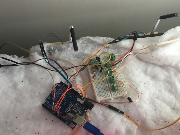
For this to work, the LEDs have to be against the wall facing out towards the target to prevent signal bouncing off the wall and hitting the other items. However, I want to sit comfortably across the room with my computer so I can type in the commands and see all the responses by the targets in front of me. This requires either a really long USB cable to reach an Arduino located with all the other components along the back wall or some really long connecting wires for all the LEDs to run them across the room to an Arduino attached by a normal length USB cable to the computer. Neither of those options are practical.
After fussing with the situation for a while, I finally settled on dedicating one Arduino to initialize the Made with Magic targets and to set the default lighting effects. That Arduino is located behind the targets and connects to the IR LEDs with the usual Dupont-type wires. Each time it's turned on it runs the initialization sequences and also sends out codes to set the desired lighting effects for each device. That's what you see in the video. Three of the items are running on batteries: the Earhat, Headband and Totem. The flowers (Glove components), castle (Chernabog components) and rose (WOC components) and the Arduino, all switch on around 17 sec. By about 24 sec, all the devices have been initialized:
- Earhat: pin 8 = blue
- Flowers: pin 9 = green
- Totem: pin 10 = cyan (Color not true in video. Reflection on the wall at the end is closer to the truth.)
- Castle: pin 11 = red
- Headband: pin 12 = magenta
- Rose: pin 13 = yellow
As you can see, it works. For this test I used both 180 ohm and 390 ohm resistors. Both appear to do just fine. Expand the video to full screen and you should see there, up against the wall, those 'spotlights' aiming at each target and making the magic happen.
Altering ArduinoMWMController.ino to enhance initializer duties
To enhance the program from part 1, ArduinoMWMController.ino, to include setting display effects, find the following line near the top:
#define ALLLEDS 0
Then insert the following directly below that line:
//skip spaces between codes to save memory. initialize to solid color Uno pins
char *fxcmds[] = {
"24",//first one is just a place holder
"8C0FA9112461D005FF",// pin 8
"8C17A9192462D005FF",// pin 9
"8C1FA9212463D005FF",// pin 10
"8C27A9292464D005FF",//pin 11
"8C2FA9312465D005FF",//pin 12
"8C37A9392466D005FF"//pin 13
};
You can substitute whatever effects you want. The 8C0FA911 part is not really required. I put it here to remind me of what the values should be when targeting from a separate controller. Starting with 24 is a good idea to wipe out any effect that might already be running. Finishing with D005FF will hold your effect and prevent the targets from slipping back into demo mode after 2 minutes. What goes between the 24 and the D005FF is up to you.
Now find the configLED function and replace it with this version:
void configLED(int ledNum) {
byte idcmd[] = {0x93, 0xD1, 0x29, 0x10, 0x20, 0x00};
idcmd[3] += (ledNum) * 16; //A9 goes up in 0x10/2 increments from 0x20
idcmd[4] += (ledNum) * 16; //AA goes up in 0x10/2 increments from 0x30
idcmd[5] = calcCRC(idcmd);
sendCodes(idcmd, ledNum); delay(100);
sendCodes(idcmd, ledNum); delay(100);
sendCodes(idcmd, ledNum); delay(100);
byte * cmd = fixCodes(fxcmds[ledNum]);
sendCodes(cmd,ledNum);delay(100);
sendCodes(cmd,ledNum);delay(100);
sendCodes(cmd,ledNum);delay(100);
if (showPrompts) {
Serial.print(" pin "); Serial.print(ledPins[ledNum]);
Serial.print(": A9 = "); Serial.print(idcmd[3] / 2, HEX);
Serial.print(" AA = "); Serial.println(idcmd[4] / 2, HEX);
//Serial.print(" port:");Serial.println(ledPort[ledNum],BIN);
}
}
Save those edits as ArduinoMWMInitializer.ino and then upload the script to your Arduino. It now functions as an enhanced initializer and controller. If you want to go with a dedicated initializer, other parts of the script can be changed and code can be added to the Loop function to refresh the initialization every hour or so. Have a look at this version of ArduinoMWMInitializer.ino as an example.
Alter a copy for a second Arduino so initializations aren't overwritten
ArduinoMWMController.ino comes with code to send out initialization data. If another Arduino has already set those initializations, you won't want to mess those up when using a different controller. We need to comment out the part that wants to mess things up. Find the following code and comment it like so:
// for (i = 1; i < pinTotal; i++) {
// configLED(i);
// }
Save the changes and then upload it to whichever Arduino you'll use to blast codes to all the targets at the same time.
Using code to dynamically target initialized Made with Magic items
Once the individual MWM items have been successfully initialized, any one of the them can be singled out after that by using the appropriate 8C XX A9 YY command. Check the second table above for the right values to use for each of the targets associated with their respective pins. For example, sending 8C 17 A9 19 24 67 D0 05 FF to all the targets will cause the flowers in the video, and only the flowers, to turn white. Then sending 8C 27 A9 29 48 88 D0 05 FF will cause the castle to start displaying the 48 88 effect - and only the castle. Substitute any valid codes you'd like for any of the targets you'd like. The good folks at Disney Imagineering designed things to work this way. Kind of fun, isn't it? Enjoy.
