Ancient History - circa 2012
The 'Glow with the Show' technology (as Made with Magic was originally called) attracted almost immediate interest from the maker/hacker communities. After all, what self-respecting techno-brat could possibly resist exploring a new, low cost, remotely controllable LED controller that also features multiple standalone effects and peer-to-peer synchronization? The first device tear downs were published in short order.
It quickly became apparent that infrared light is how the signals are transmitted. Specifically, the infrared light used has a wavelength of approximately 940nm - a logical choice as it's beyond the visible range of the human eye and doesn't distract from the main light shows. Furthermore, the signals were found to be modulated with a transmission frequency of ~37kHz. Data is sent using a standard serial protocol with a data rate of 2400 BAUD.
Having established all that, the MWM commands could be captured and examined. The MWM command syntax was starting to reveal itself. The final piece of the MWM sytax puzzle concerned how to calculate the checksum byte at the end of each MWM command. Once that was determined, it became possible to write code and actually test out theories on what the MWM commands do by sending those commands to the MWM products and watching their response. Understanding of the MWM command language progressed rapidly after that. You can read about how all this unfolded in the thread from the doityourselfchristmas.com forum.
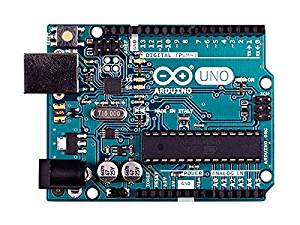
The Arduino UNO controller
 The first set of software tools for working with Made with Magic products, that I'm aware of, was provided by Jon Fether. He published a series of scripts for the Arduino UNO microprocessor that transmit MWM commands, record transmitted MWM commands and playback recordings of transmitted MWM commands. Those tools are bare-bones solutions but were more than enough to really jump start the MWM investigations. They also aren't standalone solutions. A computer is required for interacting with the Arduino.
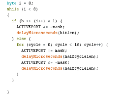
Unfortunately, those scripts haven't worked for me using the latest versions of the Arduino IDE software (1.8+). The scripts rely on the digitalWrite() instruction. That function requires quite a few processor cycles to implement and makes the execution timing dependent upon the clock speed of the microprocessor. Also, the infrared LED has to be attached to pin 3 for the scripts to work. Other functions associated with that pin have to be disabled before the digitalWrite() may be executed. That also affects the timing. I'm guessing that the authors of the Arduino IDE changed how digitalWrite() is handled in the newer versions and that sufficiently messed up the output timing of these scripts such that they no longer work.
Getting around the digitalWrite() issue
There are a couple of ways to work around the digitalWrite() problem. One way is to continue with the bit-bang approach, but dispense with the digitalWrite() function in favor of direct manipulation of the pins. The other way is to use the internal timers in the micro to cause one pin to turn on and off at a 38kHz rate, attach the anode of the IR LED to that pin and the cathode of the LED to another pin that is transmitting the codes at 2400 baud. Both of these approaches work and tend to be more reliable than using digitalWrite().
 I stuck with the bit-bang approach for a couple of reasons. The pins of the Arduinos are arranged in 'ports' of 8 pins, each. Each port is controlled by a single byte, wherein each bit corresponds to a single pin of that port. To target any particular pin(s) one simply sets the appropriate bit of that port's byte. All pins whose bits have been altered will be modified simultaneously. A consequence of this arrangement is that it's just as easy to simultaneously bit-bang all 8 pins of a port as it is to bit-bang just one! Theoretically, we could hang IR LEDs off all eight pins of a single port and bit-bang out the same command to all of them at the same time. Such an approach allows full access to all the power available to a single port. The current limit for a single Uno pin is 40mA. The limit for a single port is 150mA. So if we have 5+ pins available (30mA@), we should be able to take advantage of most of that current without damaging any pins. And, whenever it suits our needs, we can go back to addressing individual pins to modify specific targets. It's this flexibility to move between modes that is the main attraction of this approach. If all that was gained was greater signal output, we could get that from a single pin controlling a mosfet driving a bank of IR LEDs.
I've included a link to a sample script, ArduinoMWMController.ino, that implements what's been discussed and, when compiled with IDE 1.8.0, has been found to work with the following Arduinos:
- Mega2560 16MHz, 5V (2560)
- Uno 16MHz, 5V (328)
- Pro Mini 16 MHz, 5V (328)
- Adalogger 8MHz, 3.3V (32u4)
Shopping for an Arduino
Most folks who don't already own an Arduino, will probably want to start by purchasing an Uno model - if the decision is to go with an Arduino. I should mention that Arduinos aren't the only controller option. In an upcoming article, I'll discuss another option that involves a NodeMCU board. The attraction for the NodeMCU board is built-in wi-fi capability that allows control using a smart phone instead of a computer. The trade-off is a weaker IR signal and lack of ability to simultaneously bit-bang multiple pins. But, if that sounds more like what you're interested in, you might want to hold off buying an Arduino until you've had a look at that article. Or maybe just be greedy and plan to get both! No harm in that.
It used to be easier to buy an Arduino. There weren't that many models to choose from and there weren't as many manufacturers making variants of the original models and then giving their knock-offs the same name. For example, if you check on eBay, you can find an UNO, version R3, going for just under $4. Over at Amazon, the made in Italy, R3 UNO lists for $16+. Go to the Adafruit site and you'll see them listed for about $25. That's 6X what they're going for on eBay. What gives?
Part of the price differential has to do with where they're assembled. The Adafruit boards are assembled in the USA while the eBay boards usually come from China where all costs are much lower. I understand that the Adafruit folks submit royalties back to the Arduino developers while the Chinese manufactures tend to not do so. The Chinese manufacturers often cut costs by substituting the original components for less expensive work-a-likes and the overall quality tends to vary considerably. And it may take a month or two to receive an order from an Asian vendor.
If I were in the market for another Arduino Uno, I'd probably take a chance and get the Elegoo clone on Amazon. At $10.99 it's a middle of the road price and gets great reviews. It looks like it adheres to the original specs close enough that there shouldn't be any gotchas that need to be addressed to make it work with the Arduino software. It should arrive a lot quicker than the clones from China and Amazon has great return policy if there is a problem.
Still, if you are determined to try a cheap clone from Asia, head on over to the Arduino Uno tech specs and compare those to the clone's description. Pay particular attention to: "The Uno differs from all preceding boards in that it does not use the FTDI USB-to-serial driver chip. Instead, it features the Atmega16U2 (Atmega8U2 up to version R2) programmed as a USB-to-serial converter. " That's a component that is often substituted for and may lead to a frantic search for a compatible driver to get your new board to be recognized. Try to avoid such excitement by carefully reading the specs beforehand.
There are other Arduino models that could be considered, especially if you already own one. I've already mentioned, above, a couple others that I know the script will work with. It's likely that the software should work with any of the other models using the same chips, but you'd have to check the available pins, etc, to make sure and you may need to do some fiddling with the timings in the code to make things work. If starting fresh, I'd stick with the Uno and avoid unpleasant surprises that may be lurking in the hardware.
- ATmega328: Pro, Ethernet, Mini, Nano, Boardunio, Menta, Redboard, Fio, Metro,
- ATmega32U4 : Micro, Esplora, Leonardo, Flora, Pro Micro,
Selecting infrared LEDs
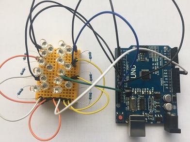
Now that you've got an Arduino Uno, you're gonna need some infrared (IR) LEDs and connecting wires (and maybe some resistors and a mini breadboard). The output wavelength needs to be 940nm. They come in two varieties: standard (20mA) and high power (100mA). There are also different beam angles to choose from. I recommend the high power LEDs like these Vishay LEDs available on eBay. That's an amazing price for 20 high power IR LEDs from a quality manufacturer!
OK. You're probably wondering if you really NEED 20 LEDs. Probably not. But, to take advantage of all the power the Uno makes available to us, it's easy to end up wanting 18. Let me explain. A typical IR LED consumes 1.5V. The Uno puts out 5V. Put three IR LEDs in series and they'll utilize 4.5V, leaving 0.5V to be handled by a resistor. The script for the Uno simultaneously emits signal to 6 pins. 6 X 3 = 18 IR LEDs that can be driven by the Uno (or any other Arduino with a 328 chip running at 5V). All that remains is to get the right resistor for the setup.
 If you got the high power IR LEDs that can handle 100mA, that's way more than the Uno can handle. So what we need is a resistor that will protect the Uno's pins that have an absolute max of 40mA. Using the ledcalc.com calculator, I get that 15 ohm resistors would give a 33mA current - which is probably as high as we would want to go. On the other hand, if you got the standard IR LEDs with max current around 20mA, a 22 ohm resistor will throttle it down to 22mA - which should be tolerable. Pick an 18 ohm resistor and the current may be around 28 mA. Your choice.
With 18 LEDs and the 15mA resistors, there's a lot of light pumped out! I point the LEDs at the ceiling in my living room and most of the MWM items in the room get the signal as it bounces around the room. But what if you only want to run a single IR LED? For one of the high power LEDs, it will need a 1/4 watt 100 ohm resistor to yield a 35mA current. Make that 180 ohms to get down to just under 20mA for a standard IR LED. And you'll probably find that the beam angle of the LED becomes much more important. I see a lot of approximately 20 degree angle LEDs. Those require a fairly accurate aim and multiple targets need to be fairly close to each other and/or close to the emitter. Wider beam angle LEDs are also available but the effective distance goes down quickly. To insure 360 degree coverage with a 20 degree beam angle LEDs would take 18 LEDs spaced 20 degrees apart. There's that number 18 again.
If you don't want to go with a full 18 LEDs to start with, consider doing 3 connected in series and attached to a single pin. Then add more later if you find you need/want more.
Setting up the Arduino IDE
To get the controller script into your Arduino, you're gonna need the Arduino software. I used version 1.8.0 to compose this script on the Windows platform. Reports have come in that other version of the IDE may not work. Let me know if you run into problems setting this up. The web programming platform isn't likely to work, either. Download the IDE software to your own PC.
There are instructions for getting things installed on your computer on their Getting Started page. Once that's taken care of, there are additional instructions on how to get scripts into your Uno. With that knowledge under your belt, you're ready to download the ArduinoMWMController.ino controller script and open it from within the Arduino IDE. You may see a message saying the script needs to be in a folder. Agree to that. Make sure your Arduino is connected to your computer. Pick your board under the tools menu. Most likely, it will be the Arduino/Genuino Uno. Click the Port menu item, also under the Tools Menu. Select the port your device is connected to. Probably only one choice listed. Venture over to the Sketch tab and find and click the Upload option. If I coded things right, there will be a compiling segment followed by an uploading segment followed by an Uploading done comment.
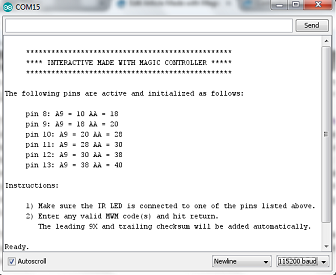
To make the magic happen, you need to open the Serial monitor by clicking what looks like a magnifying glass towards the upper right of the window. A new window will open. You may see gibberish until you go down to the drop down box in the lower right corner and select 115200 baud. It should look something like this:

If that's what you're seeing, congrats! You've arrived. Now all you need is some codes to send to your Made with Magic items.
Finding Codes to transmit
A goal of this website is to some day produce a code dictionary for the Made with Magic language. Unfortunately, that day is not today. So let me point you to more helpful pages.
- Commands for color manipulation using the two color palettes
- The Fx delays and the 48 xx special effects introduced
- Codes for creating fades without 48 xx commands
- Reset command
- Additional info about the 48 xx effects and modifiers
- lots more info in that thread after that link!
Another place to get some codes is in the MWM Shows section. Some of those shows, particularly the Osborne Lights shows, have recordings of the shows and a lot can be learned from exploring those recordings!
Finally, you can always ask here by posting in the comments section. A couple of folks who know a great deal about the Made with Magic language are frequent visitors and contributors to this site. Give 'em a try and see what they come up with.
