How this all got started
These Magical Moments Light Up pins were a subject I knew nothing about until M.T. began schooling me on the subject. Nice. Kind of established the basis for the whole Made with Magic bit. So it didn't take too much to get me interested. To get the history of these items, one needs to run into someone like M.T. and/or dig like mad through the old forum posts. I couldn't find much information about these on the official Disney site - which is not surprising as Disney tends to "bury" their dead rather quickly. But there is quite a bit about them in the forums.
The subjects
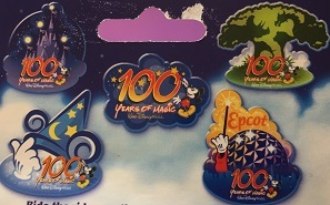 Apparently, there were at least two sets of these gizmos released. The first release came out around 2001 and consisted of a set of 5 pins - one for each of the Disney World Parks and apparently one extra just to grow on? Each pin contains a set of colored LEDs that are supposed to light up during shows, rides and/or parades. Alternatively, the lights can be elicited by swiping a finger across the front surface of the pin.
The pin is powered by two CR2032 batteries inserted in series to produce ~ 6V! That ought to do it. They're controlled by infrared signals sent out by emitters in the various Disney World Parks (no mention of these babies working west of the Mississippi. Us left-coasters are, once again, "left" out! Sniff, sniff). Reports suggest there aren't many of those emitters left at Disney World these days. That makes finding the remaining emitters something of a treasure hunt for die-hard enthusiasts to pursue.
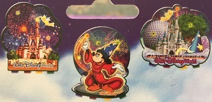 The second version of the pins came out around 2002 and consisted of only 3 pins, but those offer additional game capabilities. If you look closely at the pic, you'll see the four different colored buttons that trigger the four game modes. Three of the game modes are intended to be multi-player. Those modes rely upon the send button on the back of the pin to communicate with the other players. Like the pins before them, these pins also respond to infrared signals in the parks. There's a switch on the back for selecting either game mode or park mode. The game playing aspect isn't dependent upon Park emitters, so these game pins continue to be relevant.
Probing for answers
Both of these types of light up pins are touted to interact with the Pal Mickey device that was a contemporary of theirs. Unfortunately, all these items ceased being sold in the parks many years ago. However, it seems like there are quite a few still available via Ebay and/or that big online Seattle merchant that terminated my affiliate account. So, intrigued by my interchanges with M.T., I grabbed one of each version to see what I could find out. The logical place to start is with the game pins that brag about transmitting IR signals as part of the multi-player aspect. I really didn't know what to expect, but, being lazy, I hooked up the recorder used to record MWM shows and gave it a go. To my surprise, it worked and here's what I got:
Red game init codes: 55 AA 05 06 02 A2 00 AF
Yellow game init codes: 55 AA 05 06 03 FF 02 0F
Green game init codes: 55 AA 05 06 04 11 88 A8
So. 940nm IR, 38kHz carrier, 2400 BAUD transmitting the very familiar 55 AA-type codes. We can work with that. I notice the sequence of the 5th byte matches the sequence of the game numbers listed in the pamphlet that came with that pin. The first game is entered with the blue button and is a single player game, so no emitted signal was anticipated from that one. None of these codes impressed the other pin in the least. Totally ignored them, as might be expected. They weren't intended for it. Need to look elsewhere to get a handle on how to trigger the various display responses.
Getting results
The 55 AA 05 signature is unusual. I see a lot of 55 AA 09 and 55 AA 06 in my recordings but didn't recall the 55 AA 05 phrases. Searching all my recordings, I did find some 55 AA 05 phrases from a visit to Disney World in 2016. Testing those against the pins, I came up with two that caused them to go off:
55 AA 05 03 42 02 69 B5
55 AA 05 03 44 01 CA 17
OK. So I see an 03 in position 4 instead of the 06 sent by the game pin. Game mode vs Display mode? Could be. And in position 5 where it looked like the game selector byte might be located, we now have the potential for a 4X display pattern selector. That's particularly interesting as MWM uses a 48 XX series to select it's macros. The last two bytes before the checksum? With the game, I figured they are game specific variables. Here, maybe display pattern modifiers? Who knows?
One early observation is that these devices are MUCH less sensitive to IR signals than the MWM merchandise. I almost missed that BOTH devices responded to the two signals cuz one of the pins wasn't DIRECTLY in the path of the IR emitter. That's something to watch out for if you get the urge to dive into exploring these pins.
Running the table
The 0x4X series
Following up on the hunch that the 5th byte in the phrase may be the one that selects the displayed pattern, I tested the 55 AA 05 03 4X 01 01 CK series. The results are shown in the video. Looks like the hunch paid off.
In the process, I got to know these items a little better. Early on I came to appreciate that their IR reception is more finicky than the MWM merchandise. I found I needed to place the IR LEDs fairly close to the pins and aim them directly at the pin's IR receiver holes to get responses. Even then, I found it necessary to send replicates of each command to increase the chances of getting the pins to respond. It doesn't always work. In the video it looks like there was no pin response to the 0x44 code - but they do respond to that code with a rather nice effect. And it looks like the older version of the pins, the one on the right, doesn't respond to the blinking red code, 0x48, but in fact, it does.
Differences between the pins
One of the first things I noticed is how much brighter the older version's LEDs are. I kind of prefer them. The display segments of the older version of the pins tends to last longer than the newer pin and may be a bit quicker in the transitions between LEDs. And it seems like both pins may respond to the same command but sometimes with a different sequence. Kind of hard to tell since the LEDs are laid out differently on the two pins and the effect's timings aren't exactly the same. The newer pin, the one on the left, responds to a couple of codes that the older pin seems to ignore. So there are several noticeable differences to be mindful of.
Demo modes?
Switching the test series around to 55 AA 05 03 X0 01 01 CK gave some unexpected results. The phrase 55 AA 05 03 20 01 01 CK caused the older pin to go into an endless cycle of all of it's stored rountines. The only way I could find to stop it was to insert the plastic battery saver back into it's slot. For the newer pin, the phrase that got it going seems to be 55 AA 05 03 A0 01 01 CK. It doesn't start up immediately. It seems to pause for 20-30 sec before going into it's demo mode. Fortunately, it has a park/game switch that will coax it to stop the cycling. So far I haven't run across a code sequence that will terminate the demo mode. I suspect there must be one, I just don't have a clue what it might be.
Repeat number byte?
Testing byte 6 with the phrase 55 AA 05 03 42 0X 01 CK, it seems it determines how many times the sequence repeats before terminating. When byte 6 is 01, the display goes on for just over 30 sec. Make that value 02 and the display lasts over a minute. At 04 you'll enjoy the flashing for over 2 min, etc.
What byte 7 does I haven't the slightest. Testing a sequence with that position didn't seem to do anything. Probably depends upon the sequence and/or it's only used with other modes. Still lots to explore and figure out.
Any codes for solid colors?
Ideally, there's some codes that would return a non-blinking light. Haven't found such a thing yet. All that blinking gets annoying after a while. Seems like there should be codes to simply turn the LEDs on and off. That would be a valuable find.
Peeking under the hood
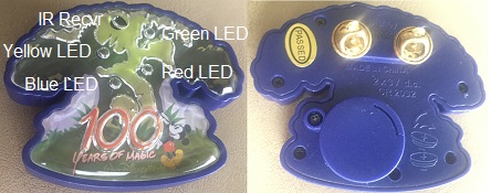 The Animal Kingdom pin was selected to see if anything could be learned by taking it apart. Let's start with the front and back images. Those 5 circular objects on the front of the pin correspond to the labeled items of the image. The back mostly features the pin attachments, the battery compartment and the screws that need removing to take this thing apart.
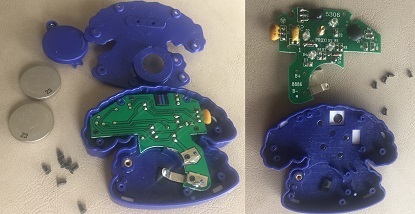 Removing the backside doesn't reveal much more than another set of screws that need removing to access the actual PCB. Once those screws were removed, the components were exposed. One unexpected finding was that those circular openings for the LEDs/receiver may actually be little lenses. If I'm remembering correctly, things looked upside down when I peeked through the IR receiver's hole. Unfortunately, we won't be figuring out what processor is in use as it is encased in a thick coat of potting plastic.
Here's a bit closer look at the front side of the actual PCB. If you want an even larger image to inspect, just click the image.
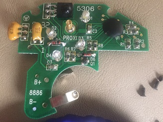
I guess one take away from the tear down is the position of the touch sensor. It appears to involve that spring located just below the IR receiver and pretty much in the middle of all those LEDs. That's handy to know as it can sometimes be a mystery as to where to touch the pin to make the lights go off.
How does this fit in with Made with Magic and the Pal Mickey stuff?
That is the question. Versions of the awesome Pal Mickey of that same era were designed to interact with these pins. Hopefully, more info about all that will be forthcoming now we have a handle on some of the basics. As for Made with Magic, the mechanics of incorporating these pins into a show should be trivial. The IR codes are no challenge to fold in. The insistence upon blinking the LEDs and display segments of at least 30 sec may pose more of a challenge. But if you're already set up to control MWM devices and are looking for something 'new' to add in, maybe it might make sense to have a look at these pins and see what you can do.
