It starts with a Glove-topus
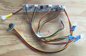 When all the wires are connected to a customized Glove board, it does somewhat resemble an Octopus, or perhaps a Jellyfish, with all those 'tentacles' flopping all over the place. They have a tendency to tangle up and get everywhere they're not supposed to be.
Fortunately, we can tame those rascals and put those pesky tentacles to good use. For this hack, we'll 'stretch' a couple of those tentacles all the way out into a couple of smaller separate lanterns to bring three lanterns together to form a single hidden Mickey Lantern.
And ends with a Hidden Mickey Lantern
This video shows the final product and goes through the codes stored in the Glove board in order to give an idea of what you'd likely see if the device is simply let run it's own internal routines.
I find the internal Glove board sequences to be more pleasing than some of the ones found in other MWM devices.
The video also demonstrates how the left/right lighting effects may be preserved by proper orientation of the 'ears'. That aspect had to be sacrificed for some of the earlier hacks utilizing other devices.
This is the most ambitious hack of the lantern series and requires the most input - but it has also proven to be the household favorite. If Mickey is popular in your household, it may well be worth the effort!
Ingredients
-
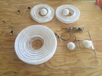 Customized Glove board
 - 4 - 5mm diffused RGB LEDs
- 2 - 6" lanterns
- 8" lantern
- 3 plastic balls
- plastic sheets cut from recycling bin contents
- packing tape
- mounting tape
- hot glue
- wire
- JST connectors
- 8 neodymium magnets
... prepare the 8" lantern
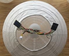 The setup for this part of the hack is not much different from what was described in the previous post from this series so the bulk of those details won't be rehashed here. Refer back to that post if you need help getting started.
What IS different this time is that all 4 board LED connectors will be used and the battery will be dispensed with in favor of wiring for external powering. Once this whole thing finally goes together, tearing it apart to replace the batteries will not seem like a good idea. A two pin 2.0mm pitch JST PH connector was used to connect to the external power line.
The wires that came with 4 pin, 1.25mm pitch sockets and mating wired plugs that were used to customize the Glove board were only about 5.5" long - not long enough to reach all the way up and into the 'ear' lanterns. Another 3-4" are needed.
I got the required extra wiring from a salvaged telephone extension cord. Some of those only have two wires, others have all 4. The ones with 4 wires are very handy for this sort of thing. I added female Dupont connectors to the opposite end of the wires from the JST plug. Then I put together 4" male/female extension cables to snake up into the 'ears'. That's only because I'm constantly connecting all sorts of things to those LED ports and need the versatility. It would be easier and more straightforward to simply solder the wires together and then solder the other ends to the LEDs.
... prepare the 6" 'ear' lanterns
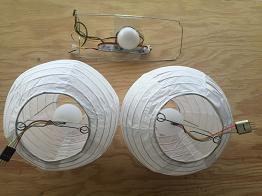 Preparing the two 6" lanterns is pretty simple. Each will get one RGB LED fed up to it by wires from the 8" lantern below. To get nice, even lighting from those LEDs, a whole Dollar Tree 'ball' is used as a diffuser. Carefully poke a hole in the 'ball' that's just large enough for the LED to enter and fit snugly.
To hold the 'ball' and the LED in roughly the center of the lantern, 1" wide strips of the scrap plastic sheeting were cut to fit between the wire frame and then taped to the frame with packing tape. Just kind of eyeball where they should go. Then use a piece of mounting tape to firmly attach the LED to that plastic strip. Packing tape didn't seem sufficient to keep the LED/ball in place.
Finally, check the eyelets on the upper rim where the metal frame inserts to hold the lantern's shape. You'll get the snuggest fit with the smallest gap between lanterns if those eyelets aren't sticking up above the rim. Ideally, they'll be slightly below the upper rim. If those can be gently bent down just below the rim, you'll get the best results.
... make the support to hold the ears in place
For this step, here's the deal. The two LEDs in the 8" lantern need to point out at right angles from the internal wire frame to minimize creating shadows from those wires. And we want the two 6 inch 'ear' lanterns to line up with those LEDs below so we get that nice left/right effect. But that doesn't give us a good attachment point for those two upper lanterns. So something is needed that can serve as support but isn't so bulky that it interferes with the looks.
The best I could come up with is a clear plastic strip with neodymium magnets hot glued in place so they'll bind to the upper lantern frame and hold it snugly against the lower lantern. The dimensions needed will vary with each setup. Substantial variations from lantern to lantern have been noted. So predicting the exact measurements isn't possible. But here's some guidelines for how to approach making that support.
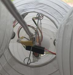
- Cut out a piece of scrap plastic sheeting with width that should probably be between 1-2" and length around 9".
- Find the center of the piece and line it up over the top of the 8" lantern and mark right above where the V notch is in the top frame. Cut a hole there that's big enough for the power cord to pass through. I used a paper hole punch which worked for the 18 gauge wire I used.
- Line up the plastic on the top of the lantern, once again, and mark where the base of the hook is located and punch a hole to let that pass through. Make sure that the plastic support is lined up in the same direction as the LEDs below before cutting that hole.
- Now determine where to put the magnets. The areas with the most metal to bind the lantern to the magnets are the two areas where the metal frame inserts into the circular eyelets on the edge of the upper opening. With the plastic strip in place and resting on the outside of the 8" lantern, figure out where you want the two top sets of magnets to go. They need to be WITHIN the opening of the 8" lantern to get the snuggest fit. Those 'horns' of the inner frames, that poke through the circular eyelets, may cause a significant gap between lanterns if that top magnet is placed outside the opening of the lower lantern. With my build, the distance to the center of the top magnet from the hole where the power cord will go was 1.5". Mark the placements and then hot glue the first two magnets to the UNDERSIDE of the strap.
Once those have cooled and are no longer tacky, put the plastic strap back in place on top of the 8" lantern. Put another pair of magnets on the topside of the pair you just hot glued. Now, you should be able to position one of the 6" lanterns in place and have it bind to those magnets. Work down to the other horn in the opening of the 6" lantern on the far side from the one now bound to the magnets and mark the strap where that horn touches the strap. This is where the next magnet will be placed. After marking positions for both 'ear' lanterns, remove the strap and hot glue a magnet to the UNDERSIDE of the strap for each of the new marks.
... put it all together
We're almost there. Feed the power wire through the hole cut in the plastic strap and connect it to the Glove board.
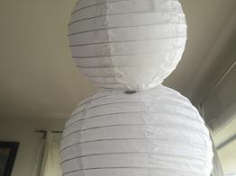 Work the hook on the frame through the hole cut for it in the plastic strap. Now feed the ends of the plastic strap INSIDE of the 8" lantern's top opening. Tilt the 8" lantern to one side such that one of the straps droops toward the side of that lantern. Take one of the remaining magnets and move it along the outside of the 8" lantern until it attracts and binds to the inner magnet on the strap. Repeat for the other strap on the other side.
With those magnets in place, it should now be possible to position the 6" 'ear' lanterns and have them sufficiently bind to the 8" lantern without need for anything else to hold them in place. To diminish the gap between the 'head' and 'ear' lanterns, position those 'horns' so they are binding to the sides of the magnets and not to the surface of the magnet. As shown in the photo, the magnet may be visible even when the 'ear' lantern is in place. If that detracts from your enjoyment, you could always wrap in in some sort of white paper to make it blend in a little better. From a distance most folks are likely to view it from, it isn't very noticeable.
... power it up and enjoy!
A twist tie was used to connect the power cord to the metal hanger hook to provide a little bit of strain relief. A zip tie would probably work better.
The power options are up to your preferences. Could be a battery pack or, as in my application, an old PC power supply with a 3.3V output. If you need ideas, check the post on powering Made With Magic Devices.
Next up - obedience school
Inevitably, there comes a time when the lights your proud creation wants to flash just don't match what your mood desires. What works perfectly at 10pm in one of the parks, doesn't cut it at 2am back home after a hard day. A resolution is made to take command and teach the young upstart how to do your bidding. That's what we'll take a look at in the next few posts.
Others in this series
- part 1 - Lanterns + MWM's Possums: Wand and Paintbrush
- part 2 - Lanterns + MWM's Halibuts: Headband, Glove and WOC Sipper
- part 3 - Lanterns + MWM's Yogis: Ear Hat v1.6, Ear Hat v2.2 and Customized Glove
- part 5 - Lanterns: House-breaking - enforcing a 'code' of conduct
